
Microwave Link
-Pre Deployment, Deployment, Post Deployment
As the most critical step in any network deployment or upgrade, the planning and design phase provides the essential foundation for your future network build.
Maclinks's planning organization delivers the highest levels of expertise, with extensive experience in the planning and design of thousands of communications networks around the globe.
Planning and Design Benefits
- Minimize your total cost of ownership through network design optimization
- An in-depth understanding of your requirements ensures a successful deployment day one
- Understand alternative designs options and the implications to your network
- Meet the capacity and resiliency requirements of current and future service offerings
The maclinks's line-of-sight service is intended to provide an accurate assessment of the viability of a planned link between two points for microwave deployment. While as much detail as possible is considered during the planning stage, a validation of the link with an on-site visit and visual verification is a critical step in the deployment of the microwave network.
The line-of-sight service includes:
- On-site visit and visual verification of the two end points
- Confirm Line-of-Sight at identified radiating centre line and minimum antenna height
- Ensures no obstructions in the path such as trees, current structures at the time of survey
- Using best judgement and tools, ensure that adequate Fresnel zone clearance is observed for each on path object
- Recommended placements at each endpoint for the microwave antenna equipment
- General Pass/Fail on Line-of-Sight for specified path
- Provide alternatives if planned path does not achieve line-of-sight
- Digital photos for the link, 360 degrees, near and far field
- Comprehensive line of sight survey report
- Flash LoS – Crews climb to the required mounting heights simultaneously while flashing occurs on one end while the far side team takes photo’s
- Path Drive – Intended for longer paths or where a lower cost option is required by customer
Site survey service is intended to verify that a particular site is suitable installing and deploying a microwave backhaul endpoint. The output of the survey would include as a minimum:
- General suitability for microwave installation including proximity to nearby objects, existing equipment, potential radio interference, and any other objects which may impede the proposed microwave link
- Collect data to enable civil engineering to supplement construction drawings on mast locations, site modifications and radio/antenna installation locations
- Confirmation and documentation of conduits, power, grounding, structures, documenting any deficiencies and changes required to enable the site to be ready for microwave installation
- Photographs of the site, documented with any observations
- Site survey report packaged and submitted
Andorson
Logistics services are intended to manage all microwave equipment and components intended for installation and commissioning during the build-out deployment phase within a given market. The services are intended to be located in market in customer provided warehouses. Alternatively, warehousing space can be obtained as a separate service.
The scope of work included with logistic and pre-staging services:
- Receive raw materials (radios, antennas, cables),
- Once provided with Notice-to-proceed, kit into microwave links as per provided design
- Set-up and validate equipment operation
- Pre-label equipment
- Capture serial numbers per respective site, record in tracking tools
- Manage and track equipment pickup and obtain signatures on delivery to crew
- Manage all inventory tracking
Maclinks will perform an interference analysis to determine frequencies that will not cause harmful interference to proposed microwave paths within the designed network.
Microwaves are a form of electromagnetic radiation with wavelengths ranging from as long as one meter to as short as one millimeter; with frequencies between 300 MHz (0.3 GHz) and 300 GHz.This broad definition includes both UHF and EHF (millimeter waves), and various sources use different boundaries. In all cases, microwave includes the entire SHF band (3 to 30 GHz, or 10 to 1 cm) at minimum, with RF engineering often restricting the range between 1 and 100 GHz (300 and 3 mm).
The prefix micro- in microwave is not meant to suggest a wavelength in the micrometer range. It indicates that microwaves are "small", compared to waves used in typical radio broadcasting, in that they have shorter wavelengths. The boundaries between far infrared, terahertz radiation, microwaves, and ultra-high-frequency radio waves are fairly arbitrary and are used variously between different fields of study.
Beginning at about 40 GHz, the atmosphere becomes less transparent to microwaves, due at lower frequencies to absorption from water vapor and at higher frequencies from oxygen. A spectral band structure causes absorption peaks at specific frequencies (see graph at right). Above 100 GHz, the absorption of electromagnetic radiation by Earth's atmosphere is so great that it is in effect opaque, until the atmosphere becomes transparent again in the so-called infrared and optical window frequency ranges.
The term microwave also has a more technical meaning in electromagnetics and circuit theory. Apparatus and techniques may be described qualitatively as "microwave" when the frequencies used are high enough that wavelengths of signals are roughly the same as the dimensions of the equipment, so that lumped-element circuit theory is inaccurate. As a consequence, practical microwave technique tends to move away from the discrete resistors, capacitors, and inductors used with lower-frequency radio waves. Instead, distributed circuit elements and transmission-line theory are more useful methods for design and analysis. Open-wire and coaxial transmission lines used at lower frequencies are replaced by waveguides and stripline, and lumped-element tuned circuits are replaced by cavity resonators or resonant lines. In turn, at even higher frequencies, where the wavelength of the electromagnetic waves becomes small in comparison to the size of the structures used to process them, microwave techniques become inadequate, and the methods of optics are used.
High-power microwave sources use specialized vacuum tubes to generate microwaves. These devices operate on different principles from low-frequency vacuum tubes, using the ballistic motion of electrons in a vacuum under the influence of controlling electric or magnetic fields, and include the magnetron (used in microwave ovens), klystron, traveling-wave tube (TWT), and gyrotron. These devices work in the density modulated mode, rather than the current modulated mode. This means that they work on the basis of clumps of electrons flying ballistically through them, rather than using a continuous stream of electrons.
Low-power microwave sources use solid-state devices such as the field-effect transistor (at least at lower frequencies), tunnel diodes, Gunn diodes, and IMPATT diodes.Low-power sources are available as benchtop instruments, rackmount instruments, embeddable modules and in card-level formats. A maser is a solid state device which amplifies microwaves using similar principles to the laser, which amplifies higher frequency light waves.
All warm objects emit low level microwave black-body radiation, depending on their temperature, so in meteorology and remote sensing microwave radiometers are used to measure the temperature of objects or terrain .The sun and other astronomical radio sources such as Cassiopeia A emit low level microwave radiation which carries information about their makeup, which is studied by radio astronomers using receivers called radio telescopes.The cosmic microwave background radiation (CMBR), for example, is a weak microwave noise filling empty space which is a major source of information on cosmology's Big Bang theory of the origin of the Universe.
Microwave Link Installation
Microwave link installation is performed by Maclinks qualified and certified crews. Crews can be scaled to meet the build-out market demand and project schedule. All resources within a crew adhere to all local safety laws and carry safety certifications.
Microwave link installation includes:
- Rooftop, tower or monopole locations through use of riggers (crane, bucket extra)
- Installation of dish antenna on existing antenna mast
- Installation of ODUs and IDUs as per link design
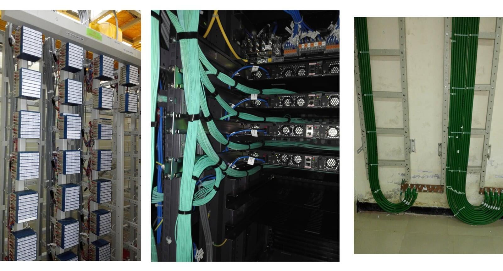
- Running, labeling and securing of required cables (Cat5e, IF, fiber, power)
- Termination of connectors at ODU and IDU ends, with assurance of connectivity, strain relief, taped/waterproofed/tie wrapped.
- Installation of grounding cable
- Installation of DC power cable from customer provided power source and breakers
- Validation of correct power and grounding of system
- Validation all of cables through cable testers
- Confirmation of installation quality through established punch-list
- Detailed photographs of installation
- Comprehensive MOP – outlining installation procedures and configuration details
- Upgrades from 1+0 to 2+0, capacity upgrades etc., Maclinks will construct a comprehensive MOP, obtain diagnostics prior and post services work delivered
Link Alignment and Testing
After microwave link installation, We performs microwave link alignment and testing.
The link alignment and testing service includes:
- Precise alignment of antennae at both ends of the link
- Any final radio configurations as required
- Validation of traffic continuity of the link at the link designed throughput speeds
- Measurement of latency and throughput values using standard RFC tests
- 1 (one) hour Bit Error Rate test to confirm error-free traffic for the link between link demark endpoints (RJ45 connector terminating at local switch or BTS)
- Completion of Acceptance Test Plan
Program Management Office (PMO)
The PMO resource team provides a single point of contact between customer, Maclinks and market project resources.
Responsibilities include:
- Tracking, managing, and reporting on progress all aspects of the project.
- Overall project plan, communications, costs, resources, quality, customer satisfaction, deliverables, change orders, oversights, issues
- Regular reporting on project KPIs and status
- All regional project manager and sub-resources report to this PMO resource
Regional Project Manager (RPM)
The Regional Project Manager is an assigned resource which can technically manage all local resources within a given market.
Responsibilities include:
- Tracking, managing, and reporting on progress all aspects within the assigned market area
- Ensures all resources are performing daily as per PMO project plan
- Manages local resources to ensure fully trained, meets or exceed all safety regulations
- Ensure install quality meets or exceeds specifications
- Change orders, costs within assigned market area
- Human resources within assigned market area
- Ensures all local crews have required equipment, tools and resources
- Provides final closeout package, as-built, for each completed microwave link installation
- Resolve local market issues are required, and escalates issues which cannot be resolved
Acceptance testing
With the completion of each microwave link installation, Maclinks provides a complete Closeout Package (COP) which includes as a minimum:
- Marked up (customer supplied) construction documentation showing “as-built” for each site
- Microwave test results as output from link testing (RFC, BER)
- Radio configuration and diagnostic files, including RF actuals vs. RF design parameters
- Photos of complete installation – cabinet, lines, tower etc.
- Site coordinate information
- Serial numbers of each product deployed
Microwave Link Decommissioning
Microwave link decommissioning is performed by Maclinks qualified crews. Crews will remove existing legacy equipment and transport in accordance by customer.
Maclinks offers a comprehensive suite of technical support services to meet the needs of organizations.
Our technical support is complimented by a range of professional services including on-site support, on-site field audits, commissioning and turn-up services.
Overview
Maclinks continues to provide an industry-leading customer experience in offering Harmony Care, a complete package tailored towards the needs of operators today and tomorrow.
Harmony Care is a comprehensive and flexible program that can be customized to suit a variety of specific needs and budgets, focusing on:
- CAPEX-extension; extending the life and getting the most out of your network investment
- Minimizing network down-time and exceeding customer SLA’s
- Relieving the operational load associated with troubleshooting, repair, and hardware replacement
- Offering peace of mind that technical experts are available 24x7 to assist
IBS
- Implementation and Optimization
The goal of any idea or project is functional solution. To meet the last segment in our offer we provide you technical qualified and dedicated professionals who will implement designed system.
Working with cellular carriers is very important for the performance and reliability of your new system and the performance of the carriers’ network.
maclinks has in-house and certified installers to commission your in-building wireless system. We can work with your installation team as well by providing them with detailed installation diagrams to run cabling and mount equipment in pre-determined locations.
During the system commissioning we will be on-site to work with the carrier, test components, tune your system to its peak performance and record the information required by your carrier(s). Subnet works closely with the cellular carriers from system design to the commissioning of your new in-building solution providing you with a carrier-approved system that will leave you with a high level of customer satisfaction.
BTS
- Installation and Commissioning
Maclinks is known to be one of the renowned service providers for undertaking a complete 2G, 3G and 4G NodeB installation accessories projects for diverse telecom networks.
We have employed a strong team of highly professional and experts who have extensive domain specialization and vast product knowledge in their respective fields and make sure that we meet the specific needs and demands of our clients within the stipulated time frame, in order to attain maximum customer satisfaction.
Services Include:
- AC/DC power installation and maintenance
- BTS Installation, Commissioning & integration
- Fault diagnosis and rectification
- Site Alarm installation & commissioning
- Multi-vendor swap outs & upgrades
- Cell site maintenance
- Feeder testing.
BTS Indoor Installation, MBTS/BBU Site Indoor Installation and Commisioning,RFS/RRU Tower Top Mounted ,Commissioning, Integration & ATP Sign-Off. Un-packaging and Goods Verification and Shifting. Installation of BTS Rack. Power Cable and Grounding Cable routing and Terminate to MCB or IGB. E1 Cable Routing and Punching On DDF. Lightning Protection Box ,IGB,MCB,DDF Installation. Alarm Cable Routing and Environment Detection Sensor Fixed. RF Jumper Cable Connector Making RF Jumper Cable Routing and Connect to Existing Surge Arrestor.
- GPS Antenna Mount and cable routing. Installation for Cable Tray When it required. Labeling for all Cable and Sector. Prepare and Submit Hardware Installation Report.
- Installation of Antenna Pole or RRU or MW? Pole, Hoisting of Antennas, Connectivity & Routing of Feeder Cables, Optical cable & Power Cable Routing 3-Sectors Site Outdoor Antenna Mount. Feeder Cable Routing, Grounding and Termination. Surge Arrestor Installation and Grounding to OGB. OGB & Feeder Cable Windows Installation. Installation of Outdoor Cable Tray. Labeling For all Cable and Sector.
- BTS Power on and Card Check. Transmission Connectivity Integration. Integrate BTS with BSC. Call Tests and Record Result. Integration of External Alarm and Alarm Testing. Labeling For all Cable and Sector.
- Preparing ATP Document for Testing. Arranging Testing Record. To get Hardware Installation Acceptance Certification. Organizing ATP testing. Sign-off ATP Certificate. Preparing and Submiting Site Folder.
- BTS Site Survey, providing Site Survey detail report along with built drawings / Engineering Site Survey To work out on Site Survey Planning. Provide Detail Site Survey Report Strictly comply to Customer Requirement. Documentation For Site, Including Equipments Layout Drawing. Documentation For Indoor & Outdoor Cable Routing. Documentation For Quantities for Engineering Materials.
The ultimate goal of a RF site survey by Aster is to acquire ample information to determine the number and placement of access points that allows optimal coverage throughout the facility. The site survey is a physical survey of the customer's premises or proposed 'Hot-Zone' to identify the best possible locations to install backhaul equipment and access points to ensure 100% wireless coverage, along with maximum performance, within the desired area.
When considering the use of wireless equipment, it is extremely difficult to predict the propagation of radio waves and detect the presence of interfering signals without the use of specialized test equipment. Even if you are using omni-directional antennas, radio waves do not travel the same distance in all directions. Walls, doors, elevator shafts, people, and other obstacles offer varying degrees of attenuation, which cause the radio frequency (RF) radiation pattern to be irregular and unpredictable.
As a result, one should have an RF site survey performed to understand fully the behavior of radio waves within a facility or outdoor site before installing any wireless devices. The goal of an RF site survey is to gather enough information and data to determine the number and placement of access points that will provide the coverage required. Coverage required usually means the support of a minimum data rate in a given area. An RF site Survey will also detect the presence of radio interference coming from other sources that could degrade the performance of the wireless system.
The need and complexity of an RF site survey will vary depending on the size of the facility or site and the work that is to be accomplished. A site survey is a good idea for the use of any wireless device because without a survey, users could end up with inadequate coverage and suffer from low performance in some areas. The purchase of wireless equipment is no small expenditure, so it is best not to leave any portion of the project up to chance.
To ensure the accuracy of the final site survey report that ACCORD delivers, only the latest and most sophisticated equipment is used to check for Signal Level, Noise Level, and more importantly SNR (Signal to Noise Ratio). After the site survey, we will design the network infrastructure to fit your specific needs. Using the information obtained during the site survey, ACCORD will design a wireless network infrastructure for your specific environment that will ensure complete propagation to each of your devices.
With wireless systems, it's very difficult to predict the propagation of radio waves and detect the presence of interfering signals without the use of test equipment. Even if you're using omni-directional antennas, radio waves don't really travel the same distance in all directions. Instead walls, doors, elevator shafts, people, and other obstacles offer varying degrees of attenuation, which cause the Radio Frequency (RF) radiation pattern to be irregular and unpredictable. As a result, it's often necessary to perform a RF site survey to fully understand the behavior of radio waves within a facility before installing wireless network access points.
Single cell founction test is for verifying whether individual BTS works well or not, by making a single cell function test of BTS hardware and software.
Optimization is a series of processes for the installed system, from analysis of frequency propagation environment to system stabilization, to meet the quality and performance requirements specified in the wireless network design.
There are two types of test tool when performing the field test. It is composed of Forward Link Analysis tool and Reverse Link Analysis tool. The specification, manufacturer, quantity of each equipment will be provided in detail in separated document.
Essential items to be tested are as follows :
i. BTS Transmitter Output Measurement Test.
ii. Initial parameter establishment '(Pilot PN/System ID/Site ID/Frequency, Neighbor List)
iii. Call Origination and Termination Test.
iv. Softer Handoff Test/Antenna installation check (Direction, Tilt, Transmission Line).
v. Single Cell Coverage Test
vi. Noise Floor Tes
vii. Parameter check
Whether you have green field deployment of a new network or network expansion, or you require hot-swap of existing hardware with minimal down-time, GSM Systems will meet your expectations on time and on budget. Our experienced project managers understand the importance of a single point of accountability, and focus on coordinating resources to make sure timelines are met.
Our OEM Certified engineers each specialize in a specific OEM, and our core competency covers Ericsson, Siemens, Nokia, and Nortel.
Many firms offer expertise in radio engineering, but our competency covers core network engineering and integration with high level support available around the clock after installation is complete. For a more detailed proposal on your requirements, or for any enquiries regarding time critical projects, you can count on GSM Systems. Please contact us for more information.
We are committed to supporting rapid deployment of enhanced mobile applications. To support deployment, we will supply your operation with the expertise and products to make your next expansion or turnkey project a complete success. The end result of a partnership with GSM Systems will be benefits including reduced time to revenue, higher network capacity, fewer dropped calls and better call quality.
These services will enhance every element of your network, from microwave transmission, to antennas, BTS, BSC and MSC. Our goal is one solution - to create a comprehensive service package, which will meet and exceed your expectations.
The extensive experience and expertise that GSM Systems and our partners have gained in planning, deploying and maintaining networks, ensures the rapid rollout of highly optimized networks. We are available 24hours a day, 7 days a week to consult with your team and better understand your needs.
Fiber Optic
- Installation and Commissioning
ESPECA supplies technical services to fiber optic users primarily for Telecommunications, FTTH, FTTP, and Cellular Back-haul applications
ESPECA is a full service operation providing engineering & design assistance, fusion splicing, connectors, system documentation & characterization, systems integration, FTTx construction, provisioning & cut-over, inside wiring installations (for SFU, MDU, MTU & SMB), “Hot-Cut” splicing and emergency restorations, OTDR Testing.
ESPECA can assist our customers with engineering, budgeting, material specification & evaluation, inspections, network audits & repairs, acceptance testing and documentation.
Core Switch & Datacenter
- Installation and Commissioning
We have a large number of most Experienced Engineers for the related field. Core Network/Access/Datacom Installation also is a major task. In that point we always keep proper standard quality.
We follow the proper measurement for all Equipment’s installation during Core Network/Access/Datacom installation. Updated & Calibrated testing tools been used for all equipment’s.
- Data Center & Related Facilities.
- Power & Cooling.
- LAN-WAN Wired & Wireless Networking.
- Server & Storage Solution.
- Operating System.
- Virtualization & Database Implementation.
- Entire IT Life-Cycle.
RF and RNO
-
With new wireless communication technologies and the increasing size of radio networks, the tasks of network planning and resource optimization are b ecoming more and more challenging. This is firstly b ecause the radio resource is scarce these days due to the increasing numb er of subscribers and the many different types of networks op erating within the limited frequency spectrum. Secondly, deploying and op erating a large network is expensive and therefore requires careful network dimensioning to ensure high resource utilization. As a consequence, manual network design and tuning for improving radio resource allocation are most likely to fail in current and future networks. This necessitates developing automated to ols and optimization algorithms that are able to tackle the difficult task. Furthermore, radio network planning and resource optimization can clearly b enefit from the well-established optimization theory due to similarities in the objective-oriented way of approaching a problem, selecting the b est solution from a numb er of p ossible solutions and dealing with many restrictions. In fact, many of the network planning and resource optimization problems can b e viewed as specific applications of classical optimization problems.
In this thesis, optimization is considered as the main approach to designing and improving p erformance of wireless networks such as Universal Mobile Telecommunications System (UMTS), Wireless Lo cal Area Networks (WLANs) and ad ho c networks. The goal is to identify relevant problems for each of the technologies, formalize the problems, and find reasonable solution approaches. First, however, we will discuss what radio network planning and optimization are about, the type of problems they typically address and the typical optimization techniques that can be.
Electrical Construction
- Wiring & Installation
Maclinks has experienced and efficient work force to manage the Electrical construction at all the Telecom sites, small substation sites, core room, major power works. Follow the standard materials as per the specification is the target. Electrical construction Code and ISO9000 rules regulation also maintain at the construction site.Standard testing for each section of electrical connection maintain and the test result always supply to the customer for approval. All tests perform in front of customer and analysis carries out with specific consultant.
Decoration room, network operation room, data center, core room wiring is a major task. In this point, we always keep proper standard and use the specific wire and fittings as per approved specification. In case of under-ground or concealed wiring we always prefer getting approval from authorities before installing the materials.
We Follow the proper measurement for all electrical installation during Generator and ATS installation. Updated & Calibrated testing tools been used for all AC & DC distribution equipment’s.
an electrical installation of cabling and associated devices such as switches, distribution boards, sockets and light fittings in a structure.
Wiring is subject to safety standards for design and installation. Allowable wire and cable types and sizes are specified according to the circuit operating voltage and electric current capability, with further restrictions on the environmental conditions, such as ambient temperature range, moisture levels, and exposure to sunlight and chemicals.